Click in the tree view to display the 802.15.4 HRP UWB setup. To learn about the frame structure and where these settings are applied within that structure, see the 802.15.4 UWB concept topic.
Choices: Non-HRP-ERDEV, HRP-ERDEV BPRF, HRP-ERDEV HPRF
Default: Non-HRP-ERDEV
Coupling: Header, PSDU, and STS Settings
Sets the mode for HRP UWB PHY.
Non-HRP-ERDEV: Devices are not HRP-ERDEV.
HRP-ERDEV BPRF: HRP-ERDEV operates at the base pulse repetition frequency mode.
HRP-ERDEV HPRF: HRP-ERDEV operates at the higher pulse repetition frequency mode.
Choices: 0, 1, 2, 3
Default: 0
STS packet configuration indicates the STS position in the PPDU as well as the position of the RMARKER.
Choices: Channel 0~15
Default: Channel 0
Select the channnel number for 802.15.4 HRP UWB.
Range: 0 to 1000 µs
Default: 50 µs
Coupling: Repetition Interval
Enter the idle interval in-between frames in microseconds. When idle interval is set to zero, a continuous waveform will be generated. Use space to split different idle intervals for multi-frame case, the number of space separated values should be less than or equal to the number of frames.
Repetition Interval and Idle Interval are coupled with each other. If other waveform parameters stay unchanged, Idle Interval will be updated with the change of Repetition Interval. And vice versa, Repetition Interval will be automatically updated with the change of Idle Interval.
|
Setting |
Range |
Default |
Description |
Coupling |
|---|---|---|---|---|
|
Idle Interval (µs) |
0 ~ 1000 µs |
50 µs |
Set the idle interval in-between frames in micro seconds. When idle interval is set to zero, a continuous waveform will be generated. |
Coupled with Repetition Interval |
|
Repetition Interval |
If other waveform parameters stay unchanged, this parameter reaches its minimum value when Idle Interval is zero. |
2.909 ms |
Display the length of single PPDU frame combined with an idle interval. It will be automatically updated with the change of the waveform setting and Idle Interval. |
Coupled with Idle Interval |
Default: 2.909 ms
Coupling: Idle Interval (µs)
Displays the length of a single PPDU frame combined with an idle interval. It will be automatically updated with the change of the waveform setting and Idle Interval.
This value can be configured for your convenience. If other waveform parameters stay unchanged, this parameter reaches its minimum value when Idle Interval is zero.
Repetition Interval and Idle Interval are coupled with each other. If other waveform parameters stay unchanged, Idle Interval will be updated with the change of Repetition Interval. And vice versa, Repetition Interval will be automatically updated with the change of Idle Interval.
|
Setting |
Range |
Default |
Description |
Coupling |
|---|---|---|---|---|
|
Idle Interval (µs) |
0 ~ 1000 µs |
50 µs |
Set the idle interval in-between frames in micro seconds. When idle interval is set to zero, a continuous waveform will be generated. |
Coupled with Repetition Interval |
|
Repetition Interval |
If other waveform parameters stay unchanged, this parameter reaches its minimum value when Idle Interval is zero. |
2.909 ms |
Display the length of single PPDU frame combined with an idle interval. It will be automatically updated with the change of the waveform setting and Idle Interval. |
Coupled with Idle Interval |
Choices:
499.2 MHz for Channel 0~3, 5~6, 8~10, 12~14
1331.2 MHz for Channel 4, 11
1081.6 MHz for Channel 7
1354.97 MHz for Channel 15
Default: 499.2 MHz for Channel 0
Coupling: Channel Number
If Channel Number is 0~3, 5~6, 8~10 or 12~14, Bandwidth is 499.2 MHz. If Channel Number is 7, Bandwidth is 1081.6 MHz.
If Channel Number is 4 or 11, Bandwidth is 1331.2 MHz.
If Channel Number is 15, Bandwidth is 1354.97 MHz.
The bandwidth denotes the 3 dB bandwidth of the HRP UWB pulses.
Choice: On | Off
Default: Off
Coupling: Header Settings
This parameter determines whether to use customized header.
When this feature is on, the customized header will be used. Otherwise, the standard header defined in IEEE 802.15.4z will be used.
Choices:
Non-HRP-ERDEV: 1~24
HRP-ERDEV BPRF: 9~24
HRP-ERDEV HPRF: 1~32
Default: Code Index = 1
The index of the preamble codes used in the HRP UWB PHY channels
The length 31 code sequences are indexed from 1 to 8. The length 127 code sequences are indexed from 9 to 24. The length 91 code sequences are indexed from 25 to 32.
Choices:
Non-HRP-ERDEV: 16, 64, 1024, 4096 symbols
HRP-ERDEV BPRF: 16, 24, 32, 48, 64, 96, 128, 256, 1024 and 4096 symbols
HRP-ERDEV HPRF: 16, 24, 32, 48, 64, 96, 128 and 256 symbols
Default: 64 symbols
The number of symbols in the packet sync sequence.
Choices:
Non-HRP-ERDEV: 4, 16 and 64
HRP-ERDEV BPRF: 4
HRP-ERDEV HPRF: 4, 16 and 64
Default: 16
Coupling: Channel Number and Code Index
If Channel Number is 0~3, 5~6, 8~10 or 12~14 with Code Index of 1~8, Delta Length can be 16 or 64.
If Channel Number is 0~3, 5~6, 8~10 or 12~14 with Code Index of 9~24, Delta Length will be 4.
The length of the delta function. The delta function is used to extend the preamble code to the preamble symbol.
The value of "Delta Length" depends on values of "HRP UWB Mode", "Channel Number" and "Code Index".
Choices:
HRP-ERDEV BPRF: 0, 2
HRP-ERDEV HPRF: 1, 2, 3, 4
Default: 2
Selects the SFD sequence
Choices for Non-HRP-ERDEV:
8 symbols for the data rate of 850Kb/s, 6.81Mb/s and 27.24Mb/s
64 symbols for the data rate of 110Kb/s
Choices for HRP-ERDEV BPRF and HRP-ERDEV HPRF:
8 symbols when SFD# = 0, 2;
4 symbols when SFD# = 1;
16 symbols when SFD# = 3;
32 symbols when SFD# = 4;
Default for Non-HRP-ERDEV: 64 symbols
Default for HRP-ERDEV BPRF and HRP-ERDEV HPRF: 8 symbols
Coupling: Data Rate
If Data Rate is 850 kb/s, 6.81 Mb/s or 27.24 Mb.s, SFD Length will be 8 symbols.
If Data Rate is 110 kb/s, SFD Length will be 64 symbols.
Read only. Indicates the number of symbols in the SFD.
Choices:
Non-HRP-ERDEV: 850 kb/s and 110 kb/s
HRP-ERDEV BPRF: 975 kb/s, 7.8 Mb/s
HRP-ERDEV HPRF: 3.9 Mb/s, 7.8 Mb/s, 15.6 Mb/s and 31.2 Mb/s
Default: 110 kb/s
Coupling: Data Rate
If Data Rate is greater than or equal to 850 kb/s, PHR Bit Rate will be 850 kb/s.
If Data Rate is equal to 110 kb/s, PHR Bit Rate will be 110 kb/s.
Indicates the bit rate of PHR.
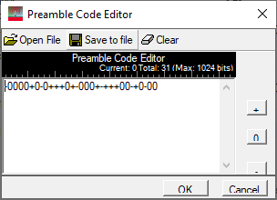
Range: maximum is 1024
Default: - 0 0 0 0 + 0 - 0 + + + 0 + - 0 0 0 + - + + + 0 0 - + 0 - 0 0
Coupling: Preamble Code Sequence Length (symbols)
Opens the ![]() Preamble Code Editor where you can edit the preamble code sequence by inputting 0, - or + directly in the form. After you click OK, the resultant code is then displayed in the parameter field.
Preamble Code Editor where you can edit the preamble code sequence by inputting 0, - or + directly in the form. After you click OK, the resultant code is then displayed in the parameter field.
"+" and "-" denote +1 and -1, respectively.
Range: 0~1024
Default 31
Coupling: Preamble Code Sequence
This parameter indicates the length of the customized preamble code sequence.
Choices:
Non-HRP-ERDEV: 16, 64, 1024, 4096 symbols
HRP-ERDEV BPRF: 16, 24, 32, 48, 64, 96, 128, 256, 1024 and 4096 symbols
HRP-ERDEV HPRF: 16, 24, 32, 48, 64, 96, 128 and 256 symbols
Default: 64 symbols
The number of symbols in the packet sync sequence.
Choices:
Non-HRP-ERDEV: 4, 16 and 64
HRP-ERDEV BPRF: 4
HRP-ERDEV HPRF: 4, 16 and 64
Default: 16
Coupling: Channel Number and Code Index
If Channel Number is 0~3, 5~6, 8~10 or 12~14 with Code Index of 1~8, Delta Length can be 16 or 64.
If Channel Number is 0~3, 5~6, 8~10 or 12~14 with Code Index of 9~24, Delta Length will be 4.
The length of the delta function. The delta function is used to extend the preamble code to the preamble symbol.
The value of "Delta Length" depends on values of "HRP UWB Mode", "Channel Number" and "Code Index".
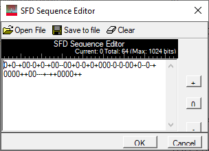
Range: maximum is 1024
Default: 0 + 0 - + 0 0 - 0 + 0 - + 0 0 - - 0 0 + 0 - 0 + 0 + 0 0 0 - 0 - 0 - 0 0 + 0 - - 0 - + 0 0 0 0 + + 0 0 - - - + - + + 0 0 0 0 + +
Coupling: SFD Length (symbols)
Opens the ![]() SFD Sequence Editor where you can edit the SFD sequence by inputting 0, - or + directly in the form. After you click OK, the resultant code is then displayed in the parameter field.
SFD Sequence Editor where you can edit the SFD sequence by inputting 0, - or + directly in the form. After you click OK, the resultant code is then displayed in the parameter field.
"+" and "-" denote +1 and -1, respectively.
Choices for Non-HRP-ERDEV:
8 symbols for the data rate of 850Kb/s, 6.81Mb/s and 27.24Mb/s
64 symbols for the data rate of 110Kb/s
Choices for HRP-ERDEV BPRF and HRP-ERDEV HPRF:
8 symbols when SFD# = 0, 2;
4 symbols when SFD# = 1;
16 symbols when SFD# = 3;
32 symbols when SFD# = 4;
Default for Non-HRP-ERDEV: 64 symbols
Default for HRP-ERDEV BPRF and HRP-ERDEV HPRF: 8 symbols
Coupling: Data Rate
If Data Rate is 850 kb/s, 6.81 Mb/s or 27.24 Mb.s, SFD Length will be 8 symbols.
If Data Rate is 110 kb/s, SFD Length will be 64 symbols.
Read only. Indicates the number of symbols in the SFD.
Choices:
Non-HRP-ERDEV: 850 kb/s and 110 kb/s
HRP-ERDEV BPRF: 975 kb/s, 7.8 Mb/s
HRP-ERDEV HPRF: 3.9 Mb/s, 7.8 Mb/s, 15.6 Mb/s and 31.2 Mb/s
Default: 110 kb/s
Coupling: Data Rate
If Data Rate is greater than or equal to 850 kb/s, PHR Bit Rate will be 850 kb/s.
If Data Rate is equal to 110 kb/s, PHR Bit Rate will be 110 kb/s.
Indicates the bit rate of PHR.
Choices:
Non-HRP-ERDEV: 2, 8, 32
HRP-ERDEV BPRF: 2
HRP-ERDEV HPRF: N/A
Default: 8
Coupling: HRP UWB Mode, Channel Number, and Preamble Code Index
Non-HRP-ERDEV:
If Channel Number is 0~3, 5~6, 8~10 or 12~14 with Code Index of 1~8, Hop Bursts can be 8 or 32.
If Channel Number is 0~3, 5~6, 8~10 or 12~14 with Code Index of 9~24, Hop Bursts will be 2.
If Channel Number is 4, 7, 11, 15 with Code Index of 1~8, Hop Bursts will be 8.
If Channel Number is 4, 7, 11, 15 with Code Index of 9~24, Hop Bursts will be 2.
The hop bursts is the number of burst positions that may contain an active burst.
Choices:
Non-HRP-ERDEV:
2, 8, 64 and 512 when Hop Bursts is 2
1, 2, 16 and 128 when Hop Bursts is 8
1, 2, 4 and 32 when Hop Bursts is 32
HRP-ERDEV BPRF: 8
HRP-ERDEV HPRF: N/A
Default: 128
Coupling: HRP UWB Mode and Hop Bursts
Non-HRP-ERDEV:
If Hop Bursts is 2, Chips Per Burst can be 2 | 8 | 64 | 512.
If Hop Bursts is 8, Chips Per Burst can be 1 | 2 | 16 | 128.
If Hop Bursts is 32, Chips Per Burst can be 1 | 2 | 4 | 32.
The number of chips in single burst.
Choices: CL3 (K=3), CL7 (K=7)
Default: CL3 (K=3)
This parameter specifies the constraint length of the convolutional code in use by the transmitter and receiver applying to the PHR and PSDU for HRP-ERDEV in the HPRF.
Choices:
HRP-ERDEV BPRF: DRBM_LP, DRBM_HP
HRP-ERDEV HPRF: DRHM_LR, DRHM_HR
Default: DRBM_LP for HRP-ERDEV BPRF
Determines bit rates of PHR field and PSDU field.
Choices: 0.5 and 1
Default: 0.5
Coupling: HRP UWB Mode and Chips Per Burst
Indicates the rate of systematic convolutional encoding.
Choices:
Non-HRP-ERDEV: 110kb/s, 850kb/s, 1.70Mb/s, 6.81Mb/s and 27.24Mb/s
HRP-ERDEV BPRF: 6.81 Mb/s
HRP-ERDEV HPRF: 6.81 Mb/s, 7.8 Mb/s, 27.24 Mb/s and 31.2 Mb/s
Default: 110 kb/s
Coupling: HRP UWB Mode, Hop Bursts, Chips Per Burst, and Viterbi Rate
Indicates the user-information rate, considering FEC.
Choices:
Non-HRP-ERDEV: 3.9 MHz, 15.6 MHz, 62.4 MHz
HRP-ERDEV BPRF: 62.4MHz
HRP-ERDEV HPRF: 124.8 MHz, 249.6 MHz
Default: 15.6 MHz
The mean PRF parameter is the average PRF during the PSDU portion of a PHY frame, which depends on the value of "Hop Bursts".
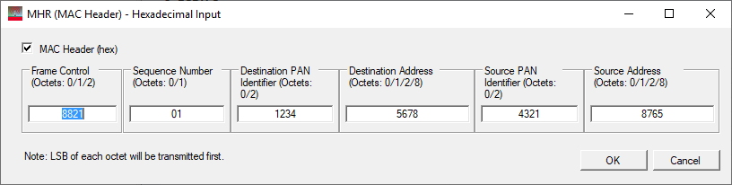
Default: 8821,01,1234,5678,4321,8765
Click the button on the right to bring up an ![]() editor to configure the MAC Header. See Figure 35 in IEEE Std 802.15.4-2011 for details.
editor to configure the MAC Header. See Figure 35 in IEEE Std 802.15.4-2011 for details.
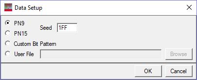
Choices: PN9 | PN15 | Custom Bit Pattern | User File
Default: PN9
Click the button on the right to bring up an ![]() editor for payload data type selection.
editor for payload data type selection.
Choices:
Non-HRP-ERDEV: 127 Octets
HRP-ERDEV BPRF: 127 Octets
HRP-ERDEV HPRF: 1023 Octets, 2047 Octets, 4095 Octets
Default: 127 Octets
Maximum Data Length of the payload field
Range:
Non-HRP-ERDEV: 0-127
HRP-ERDEV BPRF: 0-127
HRP-ERDEV HPRF: 0-1023 or 0-2047 or 0-4095
Default: 20
Enter the length of MAC payload in octets. Use space to split different length between different frame, the number of space separated values should be less than or equal to the number of frames.
Data Length indicates the total length of data, MAC Header and MAC FCS. Thus, if MAC Header and MAC FCS don't equal to zero, the maximum of Data Length should be Maximum Data Length minus the length of MAC Header and MAC FCS.
Choices: Continuous | Truncated
Default: Continuous
Select the data mode applied to MAC payload for a multi-frame waveform. Continuous mode will have data bits continuously distributed across multi-frame. Truncated mode will have the same payload data bits for all the frames, with the data size truncated for one frame.
Choices: On | Off
Default: On
Enable or disable MAC FCS in the PSDU. When turned off, it can be used to simulate an invalid FCS case, since FCS part is actually filled with user data bits. See Figure 35 in IEEE Std 802.15.4-2011 for details.
Choices: 2-octet | 4-octet
Default: 2-octet
The MAC may optionally employ the 4-octet FCS with the HRP UWB PHY in HPRF mode, but in all other HRP UWB PHY modes shall employ the 2-octet FCS.
Range:
Non-HRP-ERDEV: 0-127
HRP-ERDEV BPRF: 0-127
HRP-ERDEV HPRF: 0-1023 or 0-2047 or 0-4095
Default: 33
Coupling: Frame Length is equal to the sum of the length of MAC Header, Data Length and MAC FCS and depends on Maximum Data Length
Indicates the total length of the PSDU frame.
Choices: AES-128 STS Sequence | Fixed STS Sequence
Default: AES-128 STS Sequence
Sets the type of STS Sequence.
AES-128 STS Sequence - STS Settings will be the same as that of the SS2020 release.
Fixed STS Sequence - user-defined instead of being generated by DRBG in real time. Fixed STS Sequence should be composed of integer segments of 128 sequences, which is shown as follows.
The frame structure of Fixed STS Sequence
|
128 bits |
128 bits |
...... |
128 bits |
The length of Fixed STS Sequence should be determined by the Active Segment Length and Number of Active Segments.

If the length of the fixed STS Sequence input by users is larger than the expected length, the input sequence will be truncated. Otherwise, the input sequence will be repeated.
|
Setting |
Range |
Default |
Description |
Coupling |
|---|---|---|---|---|
|
Fixed STS Sequence |
The length of Fixed STS Sequence is between 0~1048576 bits. Each element of Fixed STS Sequence should be 0 or 1 |
0 |
The fixed STS Sequence is user-defined and static rather than be generated by DRBG during the runtime. The expected length of the fixed STS Sequence is determined by the Active Segment Length and Number of Active Segments. If the length of the fixed STS Sequence input by users is larger than the expected length, the input sequence will be truncated. Otherwise, the input sequence will be repeated. |
Coupled with STS Type. When STSType is Fixed STS Sequence, this parameter will be activated. |
Default: 0x362EEB34C44FA8FBD37EC3CA
This parameter supplies the upper 96-bits of the 128-bit value V used in the DRBG for generating the STS.
Default: 0x1F9A3DE4
This parameter supplies the lower 32-bits of the 128-bit value V used in the DRBG for generating the STS.
Default: 0x14148674D1D336AAF86050A814EB220F
Coupling: 96-bit Upper Part of V and 32-bit Counter Part
This parameter specifies the key used in the DRBG for generating the STS.
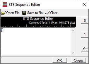
Fixed STS Sequence can be input directly or edited by STS Sequence Editor that is shown below.
Choices:
HRP-ERDEV BPRF: 8 | 64 (optional)
HRP-ERDEV HPRF: 4 | 32 (optional)
Default:
HRP-ERDEV BPRF: 8
HRP-ERDEV HPRF: 4
Specifies the length L of the delta function used to spread the 128-bit pseudo-random number.
Choices:
HRP-ERDEV BPRF: 64 in units of 512 chips (~1 µs)
HRP-ERDEV HPRF: 16, 32, 64, 128, 256 in units of 512 chips (~1 µs)
Default: 64 in units of 512 chips (~1 µs)
Active Segment Length specifies the length of active segment in units of 512 chips (~1 µs).
Choices:
HRP-ERDEV BPRF: 1
HRP-ERDEV HPRF: 1, 2, 3, 4
Default: 1
Number of Active Segments indicates the number of STS segments in the transmitted PPDU.
Range: 0~127 in units of 4 chips (~8 ns)
Default: 0
Coupling: Maximum Data Length
If Maximum Data Length is 1023, STS Additional Gap Duration can be 0~127.
If Maximum Data Length is 2047 or 4096, STS Additional Gap Duration will be 0.
This parameter specifies an additional gap in units of 4 chips (~8 ns) between the payload and the STS for HRP-ERDEV in the HPRF and STS packet configuration value of 2.
When this feature is being employed (the value is greater than 0), the feature of extending the PHY payload length field will be disabled.
Range: -300 to 300 ppm
Default: 0
Enter the shift to the standard sample rate in ppm. This error will be added to standard sample clock in the waveform header.
Range: -200 - 200 kHz
Default: 0
Enter the offset to the nominal carrier frequency in Hz.
Choices: 8-order Butterworth | Root Raised Cosine | User Defined
Default: Root Raised Cosine
Select the pulse shape filter type to be applied to the waveform.
Choices:
2 ns for Channel 0~3, 5~6, 8~10, 12~14
0.75 ns for Channel 4, 11
0.92 ns for Channel 7
0.74 ns for Channel 15
Default: 2 ns for Channel 0
Coupling: Channel Number
Pulse Duration is the coefficient used in Root Raised Cosine function, which determines the 3dB cut-off bandwidth of the pulse.
Choices: 0.5
Read only. Beta is the roll-off factor of Root Raised Cosine function.
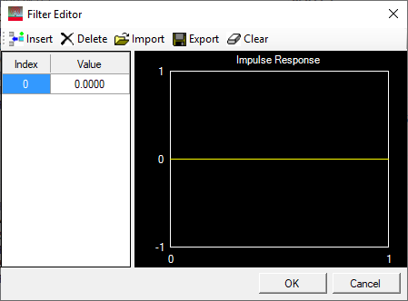
Opens the ![]() Filter Editor, allowing you to input filter coefficients or select a file that contains filter coefficients.
Filter Editor, allowing you to input filter coefficients or select a file that contains filter coefficients.
The interval between two consecutive filter coefficients equals 2 ns/Oversampling Ratio.
The maximum length of the impulse response is 8 chips (8*2 ns).
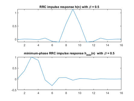
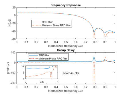
Default: On
Minimum phase is the minimum phase Root Raised Cosine (RRC) filter. The minimum phase system refers to minimum group delay of its same-magnitude(frequency response) system. An example of RRC and minimum phase RRC filters are shown below.
Choices: Off | On
Default: Off
Selects the state of the multi-path channel.
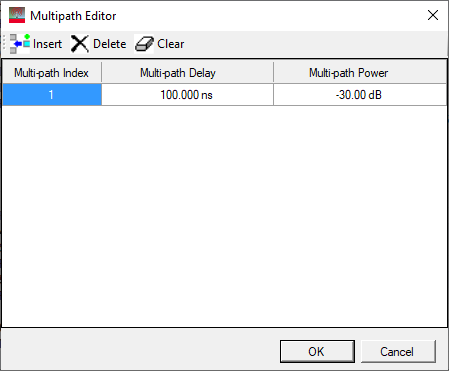
Opens the ![]() Multipath Editor where you can insert, delete, and clear channels, and edit channel settings. After you click OK, the number of paths appears in the parameter field.
Multipath Editor where you can insert, delete, and clear channels, and edit channel settings. After you click OK, the number of paths appears in the parameter field.
|
Setting |
Range |
Default |
Description |
|---|---|---|---|
|
Multi-path Delay |
0 to 100 µs |
100 ns |
Set the delay of the multi-path channel. |
|
Multi-path Power |
-100 dB to 100 dB |
-30 dB |
Set the power of the multi-path channel. |